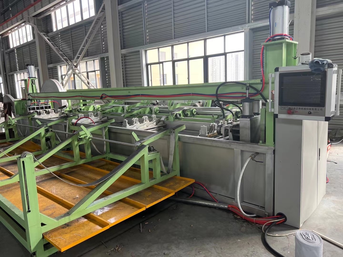
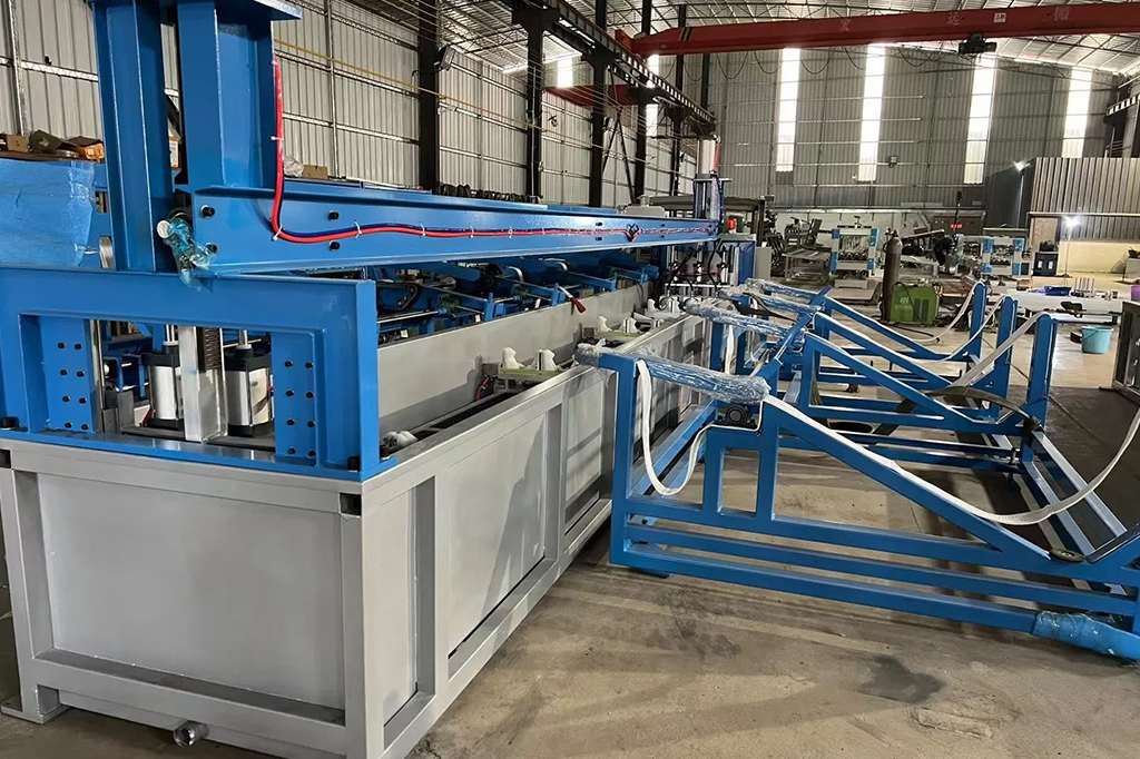
Ensuring the integrity of steel piping systems is not just good practice—it’s a necessity. Leaks, ruptures or unknown defects can lead to downtime, repair costs, safety incidents and regulatory penalties. That’s where a proper hydrostatic test comes in, and more specifically the right machine for that test. In this article we’ll explore how a steel‑pipe hydrostatic testing machine works, why accuracy is critical, and how consistent results are achieved.
The role of hydrostatic testing
Hydrostatic testing means filling the pipe or assembly with a liquid (usually water) and pressurising it to a level above its normal operating pressure, then monitoring for any pressure drop or visible leakage.
By doing so, you simulate conditions beyond daily use, exposing weak joints, welds, or hidden defects. According to one source: “the test confirms the pipeline’s ability to deal with operating circumstances by pressurising it with water and monitoring for leaks or pressure drops.”
For steel pipe manufacturers, fabricators or end‑users, this method provides a definitive pass/fail marker before a system goes live—or after maintenance, repair or retrofit.

Why a dedicated machine matters
You might ask: can’t we just hook up a pump, gauge, and some hoses? Technically yes, but a dedicated machine designed for steel‑pipe hydrostatic testing brings major advantages:
-
Consistency: a machine calibrated to deliver the correct test pressure, monitor the volume of water, log the results, hold the pressure for the required duration.
-
Repeatability: when you test many pipe segments, you want each one under the same conditions.
-
Safety and control: high‑pressure water, steel‑pipe systems, welded joints—all require proper control, safety interlocks, reliable instrumentation.
-
Automation/data logging: as noted by modern digital hydrostatic test systems: “reduces equipment and annual maintenance costs … increases efficiency without sacrificing stringent requirements needed for third‑party approval.”
Thus the “steel pipe machine for hydrostatic testing” is more than a pump—it’s an engineered system that ensures the test procedure is carried out reliably, recorded properly, and results are traceable.
Key machine components and features
Here are typical subsystems of such a machine, plus why each matters for accuracy:
|
Component |
Function |
Why it matters |
||
|
High‑pressure pump & control valves |
Generate and regulate test pressure |
Accurate pressure means the pipe is stressed to the correct level; under‑pressure may miss defects, over‑pressure may damage the pipe |
||
|
Measures the actual pressure in the system |
Pressure monitoring ensures you know exactly what the pipe sees |
||
|
Water fill / bleed system |
Ensures the pipe is completely filled, air removed |
Air pockets compressible → false readings; water incompressible → accurate detection of leaks |
||
|
Data logger / chart recorder |
|
Allows you to see pressure drop trends, document compliance |
||
|
Safety interlocks & relief valve |
Protects against over‑pressure or sudden failures |
Ensures operator safety and protects equipment |
||
|
Fixture/adaptor set for pipe ends |
Connects the machine to the pipe under test |
Proper fixturing prevents fixture leaks which would give false failures |
When operator, machine and test setup all align, the machine can deliver accurate, dependable results every time.
Typical procedure for using a steel‑pipe hydrostatic testing machine
Here’s a typical workflow:
-
Preparation
-
Inspect pipe segment: check welds, joints, flanges, end connections.
-
Clean and cap or plug ends appropriately.
-
Connect the testing machine’s hoses, fill line, bleed vents.
-
Remove air: fill with water slowly, bleed all trapped air.
As one article puts it: “air is compressible and water is not… trapped air is the leading cause of a false‑negative result.”
-
-
Apply pressure
-
Slowly bring the system up to the target test pressure (often 1.25× to 1.5× the design or operating pressure).
-
Monitor the increase in pressure and inspect all joints and connections for signs of leakage.
-
-
Hold the pressure
-
Maintain the pressure for a specified duration (e.g., 30 minutes to several hours depending on standard and pipe size) while logging pressure and temperature.
-
Analyze the pressure curve: a drop suggests leak or unacceptable deformation.
-
-
Depressurize and inspect
-
Release pressure slowly, flush and drain the system.
-
Visually inspect for external leakage or deformation.
-
Review logs: if pressure remained stable within tolerance, the pipe passes.
-
-
Report/document
-
Generate test certificate with pressure vs time chart, water volume used, operator details and pass/fail result.
-
Archive data for traceability and regulatory compliance.
-
When the machine, procedure and tracking are well‑managed, the result is a robust deliverable: “this pipeline will hold its design pressure” as one case study puts it.

How accuracy is maintained every time
Achieving accuracy repeatedly is no accident. There are several factors that must be controlled:
-
Calibration: pressure gauges, transducers, pumps must be regularly calibrated.
-
Consistent procedure: same fill‑rate, same bleed method, same pressure hold time.
-
Elimination of variables: avoid air pockets, minimise temperature fluctuations (temperature can affect pressure reading).
-
Proper fixtures: any leak at the connection point will ruin the test integrity.
-
Recording and analysing data: if previous tests show trends, anomalies can be spotted early.
-
Maintenance of the machine: worn seals, hoses or valves degrade accuracy.
-
Operator competence: human error (incorrect setup, skipping bleed) is often the cause of false failures.
When all these are controlled, the machine’s testing environment becomes repeatable and reliable—which is exactly what an end user wants.
Example of result analysis
Here’s a simplified example table of test results for five pipe segments:
Pipe ID |
Test Pressure (MPa) |
Hold Time |
Initial Pressure |
Final Pressure |
Pressure Drop |
Result |
|
A‑101 |
12.5 |
30 min |
12.50 |
12.48 |
0.02MPa |
Pass |
|
A‑102 |
12.5 |
30 min |
12.50 |
12.42 | 0.08MPa |
Pass |
|
A‑103 |
12.5 |
30 min |
12.50 |
12.30 | 0.20MPa |
Fail |
|
A‑104 |
12.5 |
30 min |
12.50 |
12.49 | 0.01MPa |
Pass |
|
A‑105 |
12.5 |
30 min |
12.50 |
12.35 |
0.15 MPa |
Fail |
Why this matters for manufacturers and end‑users
For a manufacturer of steel pipe, or a buyer / specifier of pipe to be used in oil & gas, water, chemical industries, having a reliable hydrostatic test machine and process means:
-
Fewer field failures → lower warranty claims, higher client trust.
-
Compliance with industry standards (e.g., ASME B31.3, ISO 13623) which often mandate hydrostatic testing.
-
Improved safety: less risk of catastrophic pipe failure.
-
Documented quality: test certificates lend credibility to the product.
-
Competitive advantage: customers prefer suppliers that can demonstrably guarantee pipe integrity.
If you are looking to deliver accurate results every time, the machine is only one part of the equation—procedure, documentation, maintenance and operator training count just as much. But when those elements are in place, a steel pipe hydrostatic testing machine becomes the cornerstone of your quality assurance programme. With it, you can confidently state: “This pipe is fit for purpose. It has passed the test.”