








The performance of ultrasonic pipe inspection equipment is determined by the stability of the entire inspection system rather than by probe sensitivity alone. Reliable defect detection depends on coordinated control of probe configuration, coupling consistency, pipe positioning, encoder accuracy, scanning strategy, and signal processing. Increasing gain or adding more probes rarely improves inspection reliability if these factors are unstable. A well-designed ultrasonic pipe testing machine delivers repeatable inspection results by maintaining consistent acoustic conditions throughout the inspection process, enabling higher detection accuracy, lower false-call rates, and more reliable compliance with API, ASTM, and customer-specific acceptance requirements.
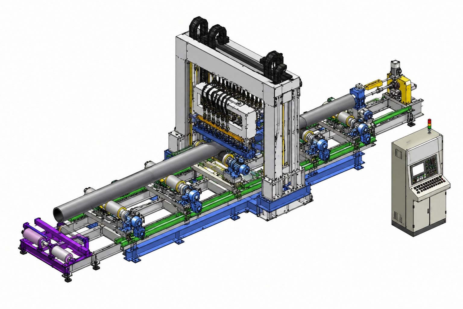
Inspection Reliability Begins Before the First Ultrasonic Pulse
One of the most common misconceptions in automated ultrasonic inspection is that detection capability is determined primarily by the ultrasonic instrument or probe sensitivity.
In practice, inspection reliability is established long before the first pulse enters the pipe.
Every inspection result depends on whether the system can maintain consistent acoustic conditions from the beginning of the scan to the final evaluation. If pipe positioning changes, water coupling fluctuates, encoder feedback drifts, or probe alignment varies during production, inspection repeatability deteriorates—even when the ultrasonic instrument itself is operating correctly.
For this reason, experienced NDT engineers evaluate an ultrasonic pipe testing machine as an integrated mechanical and inspection system rather than as a collection of independent components.
Engineering Factors Affecting Inspection Reliability
| Engineering Factor | Why It Matters | Typical Production Risk |
|---|---|---|
| Pipe Position Stability | Maintains constant beam path | Fluctuating sensitivity and inconsistent defect sizing |
| Water Coupling Stability | Ensures efficient energy transmission | Signal loss and false indications |
| Probe Alignment | Maintains designed inspection angle | Reduced coverage and missed defects |
| Encoder Accuracy | Synchronizes defect location | Incorrect defect positioning and poor traceability |
| Pipe Rotation & Feed Stability | Keeps scanning pitch consistent | Incomplete inspection coverage |
Engineering Insight: Many factories respond to unstable inspection results by increasing gain. In most cases, unstable coupling or inaccurate pipe positioning—not insufficient sensitivity—is the actual source of inconsistent detection.
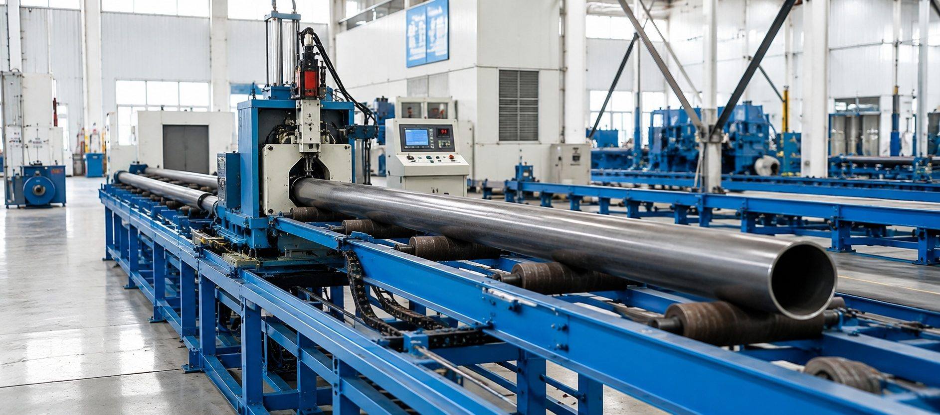
Probe Configuration Determines Coverage, Not Probe Quantity
Equipment specifications often emphasize the number of probes installed in an ultrasonic pipe inspection equipment system. While probe quantity influences potential coverage, it does not guarantee inspection quality.
The primary objective of probe configuration is to achieve complete volumetric coverage with stable signal quality and controlled overlap. Adding more probes without redesigning beam distribution may simply increase redundant inspection zones while leaving critical areas insufficiently covered.
An effective probe layout is determined by several engineering considerations:
- Pipe diameter and wall thickness
- Expected defect orientation
- Inspection standard requirements
- Production speed
- Beam overlap and dead-zone control
For example, longitudinal defects require a different beam arrangement than transverse defects. Similarly, thick-wall seamless pipes often require multiple focal paths to maintain sensitivity through the entire wall thickness, whereas thinner products can achieve full coverage with fewer inspection channels.
The best ultrasonic pipe testing equipment therefore uses the minimum number of probes required to achieve complete and repeatable coverage rather than the maximum number that can be installed.
Probe Configuration Trade-offs
| Design Choice | Engineering Advantage | Engineering Trade-off |
|---|---|---|
| More Inspection Channels | Greater flexibility for complex products | Higher calibration effort and system complexity |
| Wider Beam Overlap | Reduces missed inspection zones | Increased duplicate indications and longer data processing |
| Narrow Beam Overlap | Faster inspection and simplified analysis | Higher risk of coverage gaps if alignment drifts |
Scanning Strategy Determines Inspection Performance
For automated ultrasonic pipe inspection equipment, scanning strategy has a greater influence on inspection reliability than inspection speed.
A well-configured system does not simply scan the entire pipe—it ensures every potential defect is insonified from the correct angle, at the correct spacing, and with sufficient signal redundancy to satisfy inspection requirements.
Increasing scanning speed without adjusting pitch, encoder resolution, or data acquisition frequency reduces inspection density. While production throughput increases, the probability of missing small or unfavorably oriented defects also rises.
Experienced engineers therefore optimize scanning strategy according to the inspection objective rather than machine capacity.
Comparison of Common Scanning Strategies
| Scanning Strategy | Best Application | Engineering Advantage | Engineering Limitation |
|---|---|---|---|
| Helical Scan | General seamless and ERW pipe inspection | Complete volumetric coverage with stable scanning pitch | Requires accurate synchronization between rotation and feed speed |
| Longitudinal Scan | Longitudinal defect inspection | High sensitivity to axial discontinuities | Limited effectiveness for circumferential defects |
| Circumferential Scan | End area or local inspection | Excellent detection of transverse defects | Unsuitable for continuous full-length inspection |
| Multi-Angle Scan | API and high-specification products | Improves probability of detecting complex defect orientations | Higher calibration effort and larger data volume |
Selecting the wrong scanning strategy often produces acceptable calibration results but inconsistent production performance. Inspection procedures should always be matched to the expected defect morphology rather than adopting a single scanning method for every product.
Engineering Insight: Faster scanning does not always mean lower inspection quality. Reduced detection reliability usually occurs because scan pitch increases beyond the effective beam overlap, leaving uninspected zones between adjacent scan paths.
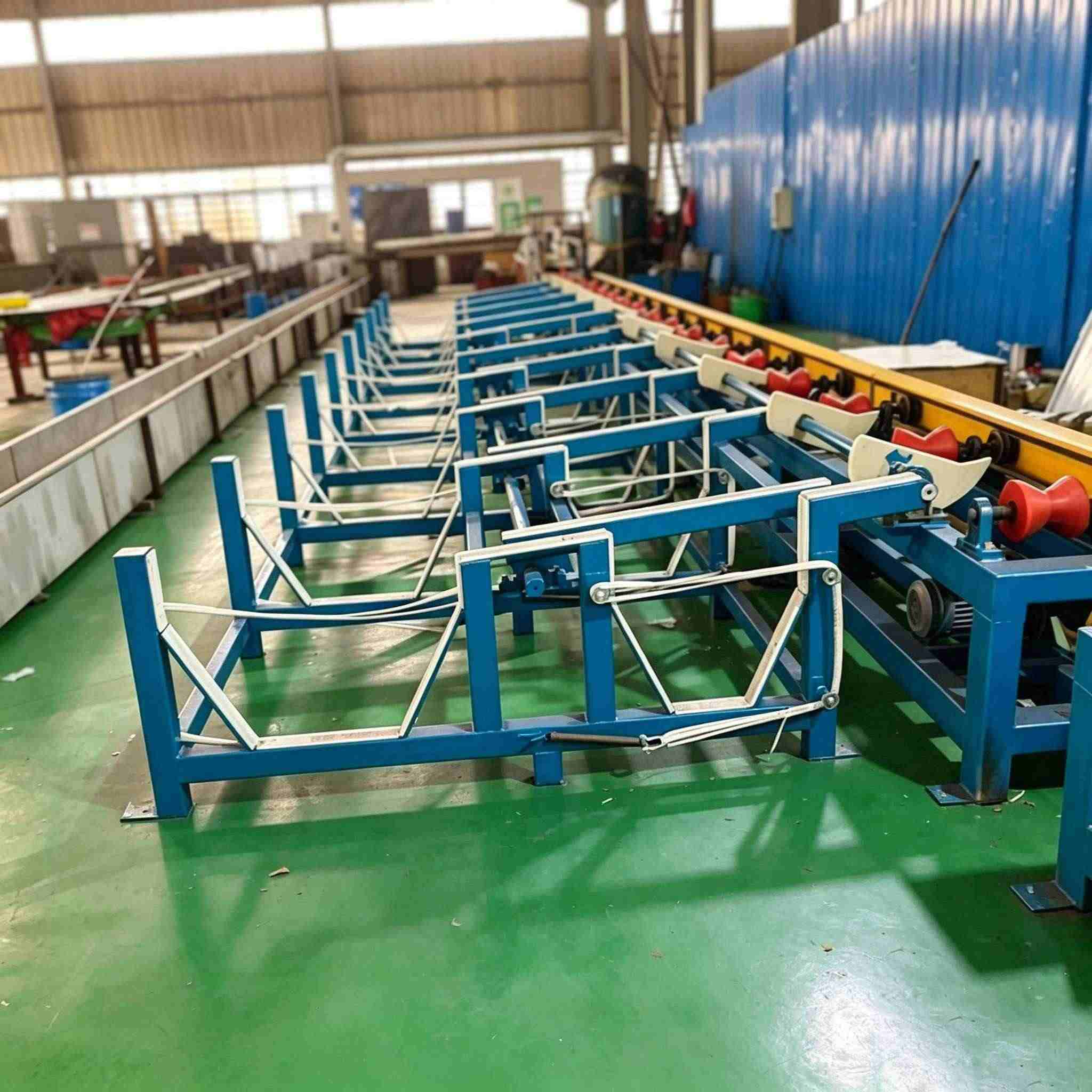
Critical Engineering Parameters That Influence Detection Accuracy
Stable inspection results are achieved when the acoustic system, mechanical system, and motion control system remain synchronized throughout production.
Among all process variables, five parameters consistently have the greatest influence on detection reliability.
Critical Engineering Parameters
| Parameter | Why It Matters | Common Mistake | Engineering Recommendation |
|---|---|---|---|
| Probe Frequency | Determines penetration depth and sensitivity | Selecting higher frequency for every application | Match frequency to wall thickness and expected defect size |
| Incident Angle | Controls defect response | Using one angle for all defect types | Select beam angle according to expected defect orientation |
| Water Coupling Stability | Maintains consistent signal transmission | Increasing gain to compensate for poor coupling | Stabilize water flow, pressure, and cleanliness first |
| Encoder Accuracy | Determines defect location and scan spacing | Ignoring encoder calibration during maintenance | Verify encoder accuracy as part of routine calibration |
| Scan Pitch | Controls inspection coverage | Increasing pitch to improve productivity | Keep pitch within effective beam overlap limits |
Although these parameters are adjusted independently during commissioning, they function as an integrated system during production.
For example, increasing production speed changes scan pitch. A larger scan pitch may require a different encoder resolution or probe overlap to maintain the same inspection coverage. Likewise, changing probe frequency without reconsidering beam divergence may reduce sensitivity in thicker-wall pipes.
Successful optimization therefore considers parameter interaction instead of treating each adjustment as an isolated setting.
Engineering Best Practices for Stable Inspection
Production data from automated pipe inspection lines shows that missed indications are more often caused by unstable inspection conditions than by insufficient instrument performance.
Maintaining process consistency is therefore more important than maximizing sensitivity.
Best Practices from Production
| Best Practice | Engineering Reason |
|---|---|
| Verify encoder calibration before every production campaign. | Incorrect position feedback affects defect location and scan overlap. |
| Monitor water quality and coupling pressure continuously. | Stable acoustic transmission is essential for repeatable sensitivity. |
| Validate beam coverage whenever pipe size changes. | Different diameters alter the effective inspection path. |
| Avoid compensating poor coupling by increasing gain. | Higher gain amplifies noise as well as useful signals. |
| Record qualified inspection parameters for each product specification. | Reduces setup time and improves production repeatability. |
Factory Practice: During troubleshooting, inspect the mechanical condition of rollers, guides, and pipe centering before adjusting ultrasonic parameters. Mechanical instability frequently appears as an ultrasonic problem, even though the instrument is functioning correctly.
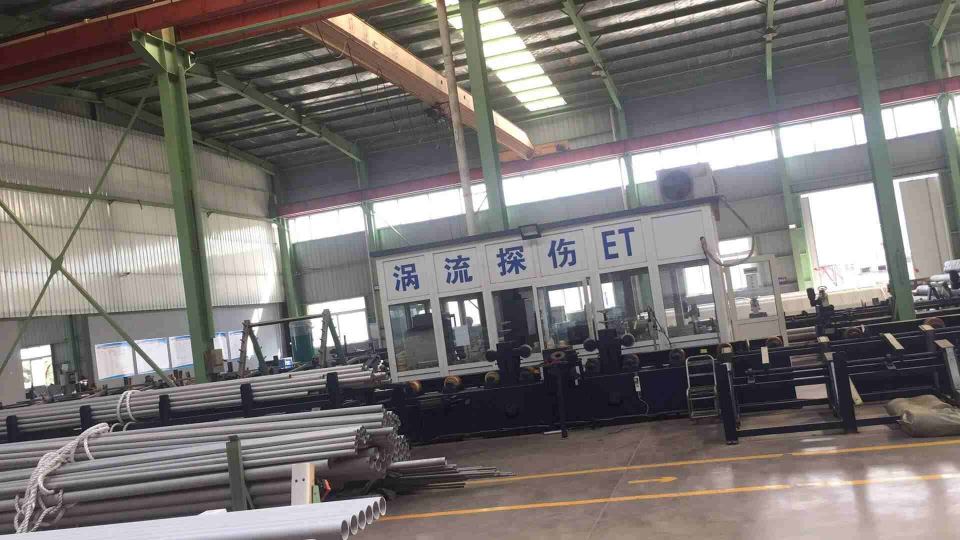
Engineering Challenges in Continuous Production
Laboratory calibration and production-line inspection are fundamentally different engineering environments.
A system that passes calibration in a controlled environment may still produce unstable results during continuous production if mechanical, acoustic, or environmental conditions change. The objective of a production inspection line is therefore not to achieve the highest sensitivity during calibration, but to maintain consistent detection capability over thousands of pipes.
The most common production issues are summarized below.
Common Production Challenges
| Challenge | Root Cause | Engineering Solution |
|---|---|---|
| Frequent false calls | Unstable coupling, excessive gain, electrical noise | Stabilize coupling conditions before adjusting sensitivity |
| Missed defects | Incomplete beam coverage or incorrect scan pitch | Verify beam overlap and encoder synchronization |
| Inconsistent defect sizing | Probe misalignment or unstable pipe centering | Recalibrate probe position and mechanical guides |
| Repeat inspections increase | Poor parameter repeatability between batches | Standardize qualified inspection procedures |
| Sensitivity drifts during long production runs | Probe wear, water quality changes, temperature variation | Schedule routine verification with calibration standards |
Engineering Insight: The most reliable inspection lines are not those operating at the highest sensitivity, but those capable of maintaining the same inspection performance from the first pipe to the last.
Applicable Standards and Equipment Selection
International standards specify inspection requirements but rarely prescribe how an ultrasonic pipe inspection equipment system should be configured. The responsibility for selecting probe arrangement, scanning strategy, and process parameters belongs to the equipment supplier and the inspection engineering team.
Standards Commonly Applied
| Standard | Primary Focus | Engineering Relevance |
|---|---|---|
| API 5L | Line pipe manufacturing | Defines inspection requirements for pipeline products |
| API 5CT | OCTG products | Covers casing and tubing inspection requirements |
| ISO 10893 Series | Ultrasonic testing of steel tubes | Specifies NDT methods and acceptance criteria |
| ASTM E213 | Ultrasonic examination of metal pipe and tubing | Provides procedures for automated ultrasonic inspection |
| ASTM E273 | Ultrasonic testing of welded tubing | Focuses on weld seam inspection methods |
When selecting ultrasonic pipe testing equipment, engineers should evaluate far more than inspection speed or the number of probes.
A practical evaluation should include:
- Inspection coverage for the required product range
- Probe configuration flexibility for future products
- Encoder resolution and positioning accuracy
- Calibration efficiency during product changeovers
- Integration with production line automation
- Long-term maintenance and spare-part availability
Factory Practice: Equipment with faster setup and stable repeatability often delivers higher annual productivity than equipment advertised with a higher maximum inspection speed.