








Before installing a pipe hydrotest machine, verify five interfaces: pipe specification, foundation and alignment, sealing system, water/hydraulic system, and electrical/control system. The actual pipe OD, wall thickness, length, weight, test pressure, and cycle time must match the machine design range.
The most critical installation risks are poor machine alignment, incorrect sealing components, insufficient water supply, trapped air, unstable pressure measurement, and incomplete safety interlocks. These should be identified and corrected before high-pressure commissioning.
1. Verify the Machine and Pipe Requirements
Do not start installation from the machine dimensions alone. First confirm the actual production range against the approved technical specification.
|
Item |
Check |
Engineering Risk |
|
Pipe OD |
Minimum and maximum diameter |
Test-head and seal compatibility |
|
Wall Thickness |
Full production range |
Pressure and loading requirements |
|
Pipe Length |
Minimum/maximum length |
Machine layout and handling |
|
Test Pressure |
Required pressure for each pipe grade/size |
Hydraulic and structural capacity |
|
Pipe Weight |
Maximum pipe weight |
Support and loading capacity |
|
Test Cycle |
Filling, pressurizing, holding and unloading time |
Production capacity |
|
Pipe Range |
Actual product mix |
Machine operating window |
Engineering action: Prepare a pipe product matrix before installation. Pay particular attention to the combination of largest diameter + highest pressure + maximum pipe weight.
2. Check Foundation and Machine Alignment
Verify the foundation before positioning the pipe hydro testing machine.
Check:
- Foundation dimensions and concrete condition
- Anchor-bolt position
- Machine centerline
- Elevation and levelness
- Pipe entry/exit centerline
- Maintenance clearance
- Drainage arrangement
- Connection points for water, hydraulics and electrical supply
The alignment chain should be:
Foundation → Machine Frame → Test Head → Pipe Centerline → Sealing Surface
A centerline error can cause uneven sealing, excessive cylinder loading, seal wear, or leakage.
Engineering action: Confirm machine level and test-head alignment with calibrated measuring equipment before final anchor tightening.
3. Inspect Test Heads and Sealing Components
The sealing system must match the actual pipe diameter, end condition and test pressure.
|
Component |
Check |
Risk if Incorrect |
|
Sealing Ring |
Size, material, hardness, damage |
Leakage or rapid wear |
|
Seal Groove |
Cleanliness and geometry |
Uneven sealing |
|
Test Head |
Centerline and surface condition |
Off-center loading |
|
Hydraulic Cylinder |
Stroke and movement |
Uneven closing force |
|
Pipe Support |
Height and alignment |
Pipe-end misalignment |
|
Mechanical Stop |
Position and rigidity |
Incorrect sealing position |
Do not install seals only by visual inspection. Verify the seal specification, dimensions and installation position against the machine configuration.
Engineering action: Check sealing components before the first pressure test and replace damaged or incorrectly sized parts.
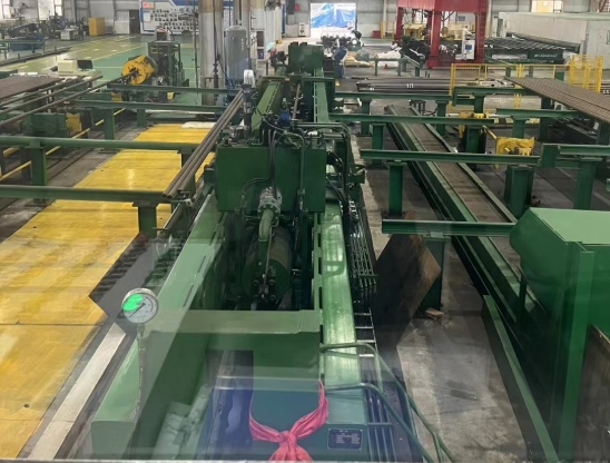
4. Verify Water and Hydraulic Systems
The test-water system and hydraulic actuation system have different requirements and should be checked separately.
Test-Water System
Verify:
- Available water volume
- Filling-line diameter
- Water supply pressure
- Drainage capacity
- Filtration/cleanliness
- Isolation valves
- Hose and pipe pressure ratings
- Air-bleeding arrangement
A restricted filling line can extend the test cycle even when the high-pressure pump has sufficient pressure capacity.
Key risk: trapped air can affect filling behavior and pressure stability. The system should allow effective filling and air removal before pressurization.
Hydraulic System
Check:
- Hydraulic oil specification
- Oil cleanliness
- HPU installation position
- Hose connections
- Hydraulic pressure
- Cylinder movement
- Leakage
- Valve operation
Engineering action: Flush and inspect hydraulic connections before commissioning; verify cylinder movement at low pressure before applying test pressure.
5. Verify Electrical, Control and Instrumentation
Before energizing the machine, confirm:
- Incoming voltage and frequency
- Electrical capacity
- Grounding
- Motor rotation
- PLC and HMI operation
- Emergency-stop circuit
- Safety interlocks
- Cylinder position feedback
- Pressure-transducer wiring
- Pressure-gauge installation
- Data recording/communication
- Remote I/O or production-line interfaces, if applicable
Pressure measurement is part of the testing system, not an accessory. The pressure sensor, gauge, PLC and recording system must provide consistent test data.
For applications governed by a specific product or customer specification, verify the required pressure measurement, holding-time control, recording and calibration requirements against the applicable edition before commissioning.
Engineering action: Perform a complete I/O and interlock test before introducing water or pressure.
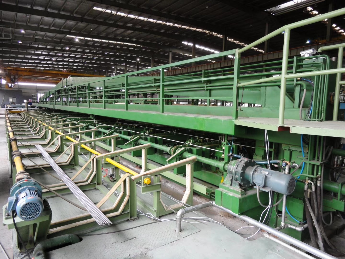
6. Pre-Commissioning Sequence
A pipe hydrotest machine should not go directly from mechanical installation to full-pressure testing.
Use the following sequence:
Foundation Inspection
↓
Mechanical Alignment
↓
Test-Head & Seal Inspection
↓
Water/Hydraulic Connection Check
↓
Electrical & PLC Check
↓
Safety Interlock Test
↓
Dry Run
↓
Water Filling Test
↓
Reference Pipe Test
↓
Controlled Pressure Test
Dry Run
Confirm:
- Pipe loading position
- Test-head movement
- Cylinder stroke
- Mechanical stops
- Pipe support movement
- Automatic sequence
- Emergency stop
- Safety interlocks
Water Filling Test
Confirm:
- Filling time
- Water leakage
- Drainage
- Valve operation
- Air removal
- Pressure-system response
Reference Pipe Test
Use a suitable reference pipe to verify:
- Pipe positioning
- End sealing
- Filling
- Pressure rise
- Pressure holding
- Pressure measurement
- Automatic release/unloading
Only after these checks should the machine proceed to normal production testing.
7. Final Installation Checklist
|
Check Area |
Acceptance Point |
|
Pipe Range |
OD, wall thickness, length and weight within machine design range |
|
Test Pressure |
Maximum required pressure within equipment rating |
|
Foundation |
Level, anchor bolts and elevation verified |
|
Alignment |
Test head and pipe centerline aligned |
|
Sealing |
Correct seal size/material and no damage |
|
Water System |
Adequate supply, filling and drainage capacity |
|
Hydraulic System |
Correct oil, pressure, connections and cylinder movement |
|
Electrical |
Power, grounding and motor rotation verified |
|
Instrumentation |
Pressure sensors/gauges installed and verified |
|
PLC/HMI |
Automatic sequence operates correctly |
|
Safety |
E-stop and interlocks tested |
|
Dry Run |
Full mechanical sequence completed |
|
Water Test |
Filling and leakage checks completed |
|
Pressure Test |
Controlled reference-pipe test completed |
Engineering Takeaways
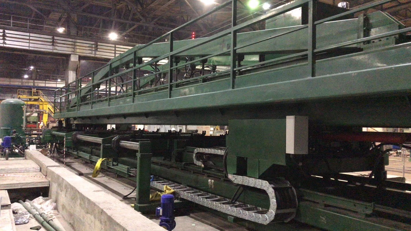
For a hydro testing machine for pipe, installation quality directly affects sealing reliability, pressure stability and test repeatability.
The highest-priority checks are:
- Confirm the actual pipe production envelope before installation.
- Align the machine, test heads and pipe centerline accurately.
- Verify sealing components against pipe size and test pressure.
- Provide adequate filling, air removal and drainage capacity.
- Check hydraulic and test-water systems separately.
- Verify pressure measurement, recording and control functions.
- Complete dry-run and water-filling tests before high-pressure testing.
- Use a controlled reference-pipe test before entering production.
A successful installation is not simply placing the machine on its foundation. The complete system must be mechanically aligned, hydraulically stable, electrically controlled and ready for repeatable pressure testing before production begins.