


A pipe testing machine for large-diameter steel pipes must do more than reach the specified hydrostatic test pressure. Its end-sealing system, pipe supports, hydraulic structure and loading arrangement must withstand the forces generated during pressurization while maintaining reliable sealing and repeatable pipe positioning.
For equipment buyers, these factors directly affect leakage risk, mechanical stability, maintenance requirements and production reliability. The correct design depends on pipe outside diameter, wall thickness, length, material, test pressure and the applicable product standard.
1. End-Sealing Loads: The First Design Check
During hydrostatic testing, internal pressure generates an axial force on each closed end of the pipe. The equipment must resist this force without excessive movement of the sealing heads or deformation of the supporting structure.
For preliminary engineering assessment, the pressure force can be estimated as:
[
F=Ptimes A_{mathrm{eff}}
]
Where:
-
(F) is the pressure-generated axial force.
-
(P) is the internal test pressure.
-
(A_{mathrm{eff}}) is the effective area enclosed by the pressure boundary.
For a simple circular sealing arrangement, the effective area may be approximated using the relevant internal diameter. The actual calculation must account for the sealing geometry and pressure boundary.
The key design implication is that the pressure force increases with the square of the effective diameter. A machine designed for smaller pipes cannot simply be scaled up by changing the sealing heads. The end frames, tie rods, cylinders, locking arrangements and load-bearing connections must all be checked for the intended operating conditions.
| Design factor | Engineering consideration |
|---|---|
| Pipe diameter | Determines the effective pressure area and influences axial load |
| Test pressure | Directly affects the pressure-generated force |
| End-sealing arrangement | Defines the pressure boundary and load-transfer path |
| Frame and tie rods | Must resist the calculated loads within allowable stress and deflection limits |
| Alignment | Must be maintained under load to prevent uneven seal compression |
The machine design should consider the complete load path from the sealing head through the structural frame and its connections. Checking individual components without evaluating the assembled structure is insufficient.
2. Pipe Support: Preventing Sag and Misalignment
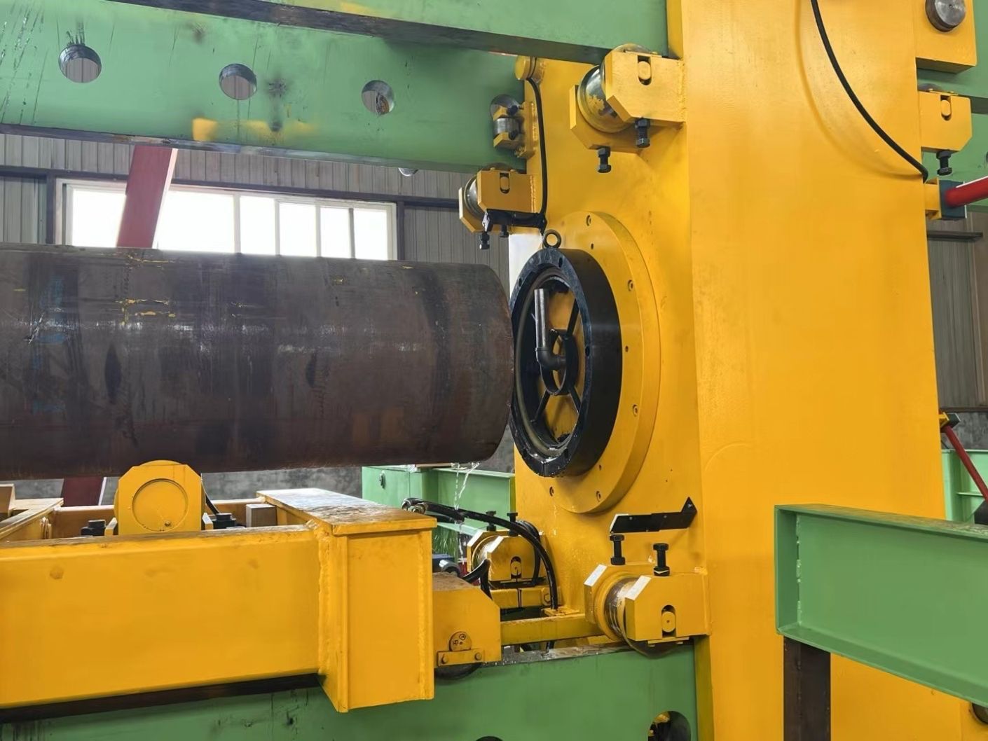
Large-diameter pipes can be heavy, particularly when long sections are filled with water. Inadequate support may cause sagging, positioning errors or uneven contact with the end-sealing system.
Support design should account for pipe length, mass, wall thickness, material properties, handling method and the distribution of support points. Long pipes may require multiple support stations or powered roller systems to maintain alignment during loading and positioning.
The supports must also suit the testing sequence. They should hold the pipe securely during positioning and pressurization without creating concentrated loads that could damage the pipe surface or cause local deformation.
For automated production lines, support height and movement must be coordinated with the loading system and sealing heads. If the pipe centerline changes as the pipe enters the test station, the sealing heads may not engage consistently.
Before approving the design, buyers should verify:
-
Whether the supports accommodate the full specified pipe-length range.
-
Whether pipe weight and water-filled conditions have been considered where applicable.
-
Whether support spacing is suitable for the pipe's stiffness and handling arrangement.
-
Whether rollers, lifting devices or positioning mechanisms interfere with sealing-head movement.
-
Whether the pipe remains correctly aligned throughout the test cycle.
3. Sealing Structure: Matching the Pipe and Test Requirements
Large-diameter pipe testing requires a sealing arrangement suited to the pipe geometry, pressure level, end condition and expected operating frequency. A seal that works well for one diameter or end configuration may not perform reliably across a substantially different range.
Possible arrangements include end-face sealing, outside-diameter sealing and other engineered configurations. Selection depends on the effective pressure area, available end geometry, allowable contact loads, pipe tolerances and the required sealing reliability.
| Sealing consideration | What the equipment designer must verify |
|---|---|
| Pipe-end condition | End-face geometry, roundness, burrs and dimensional variation |
| Diameter range | Whether the sealing head covers the required range or needs size-specific tooling |
| Seal material | Compatibility with the test medium, pressure and operating conditions |
| Contact pressure | Sufficient sealing force without unacceptable local loading |
| Seal replacement | Accessibility, replacement time and availability of spare sealing elements |
| Leakage control | Whether leakage can be detected and the system can stop safely |
A reliable seal depends on more than seal material. Incorrect centering, damaged contact surfaces, uneven compression and unsuitable tolerances can all cause leakage.
For a machine handling several pipe sizes, buyers should clarify whether diameter changes require manual adjustments, interchangeable sealing parts or automatic positioning. This affects changeover time, tooling inventory and the level of automation required.
4. Frame Design and Structural Stiffness
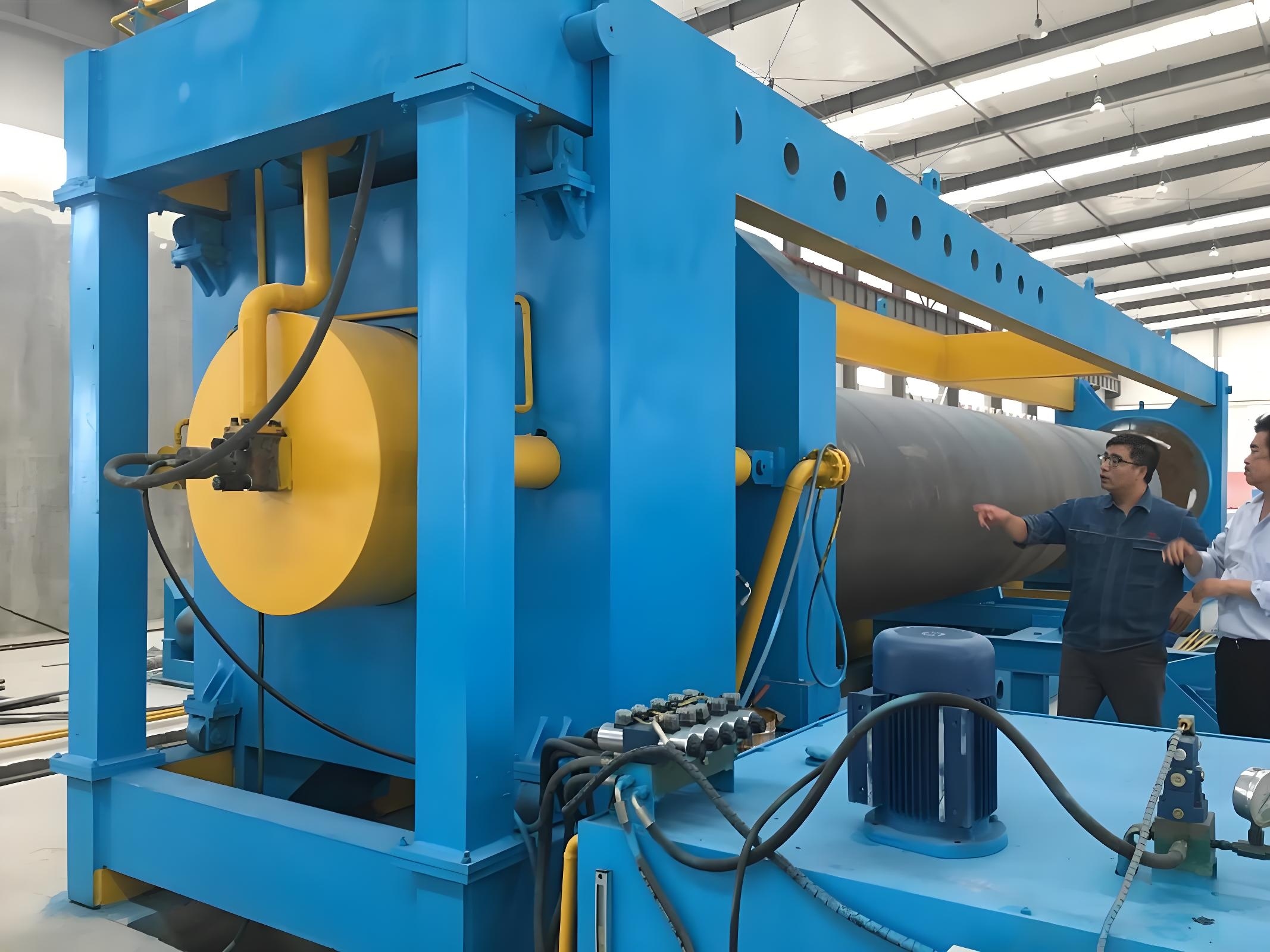
The frame must maintain the relative position of the sealing heads while carrying the pressure-generated load. Excessive deflection can disturb alignment, increase uneven loading and reduce sealing consistency.
Structural assessment should cover the main frame, cross-members, tie rods, welds, bolted connections and cylinder mounting points. The design review should consider calculated stress, deformation, fatigue where relevant and the applicable safety requirements.
The frame should not be evaluated only by its overall dimensions or apparent thickness. Load paths, connection details, material properties and manufacturing quality all affect structural performance.
For high-pressure equipment, pressure containment and mechanical load resistance must be treated as separate but related design checks. The machine's safety measures should include appropriate guarding, pressure monitoring, interlocks and controlled depressurization. Access to the test area must remain restricted until the system has safely released pressure.
5. Information Required for Equipment Selection
A large-diameter pipe hydrostatic testing machine should be configured from the actual production and inspection requirements rather than selected by diameter alone.
| Required input | Why it matters |
|---|---|
| Minimum and maximum pipe OD | Defines the operating range and sealing geometry |
| Wall thickness and pipe length | Affects pipe mass, stiffness and support arrangement |
| Material and pipe grade | Informs handling, contact and applicable testing requirements |
| Required test pressure and holding time | Determines pressure-system and structural design conditions |
| Pipe-end geometry and tolerances | Influences sealing reliability and positioning |
| Required production output | Determines loading, testing and unloading coordination |
| Automation and data requirements | Defines controls, interlocks, traceability and line integration |
The applicable product standard and customer specification must establish the required test conditions. There is no single pressure, sealing arrangement or frame configuration suitable for every large-diameter steel pipe.
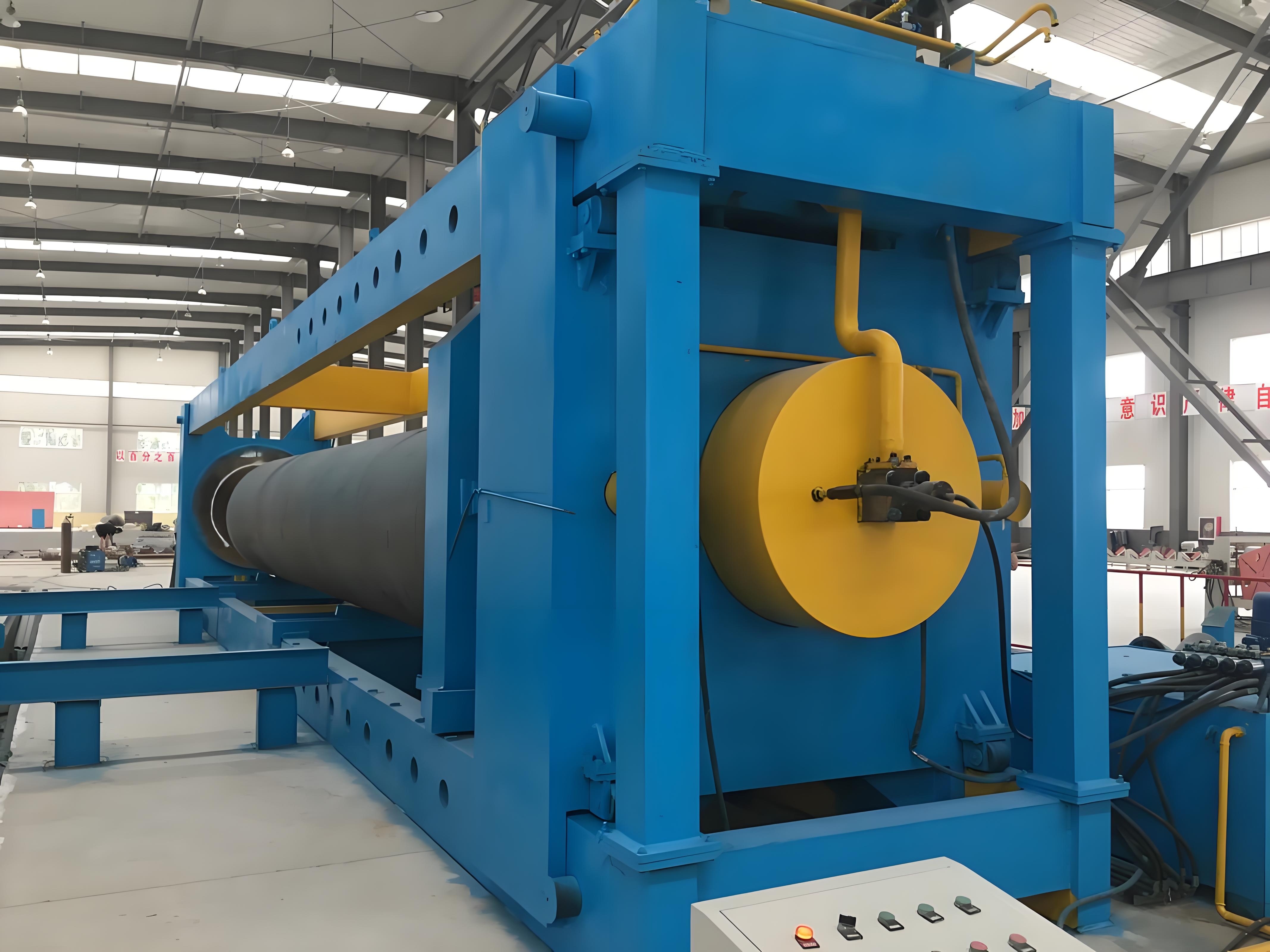
A reliable pipe testing machine for large-diameter steel pipes requires coordinated design of the pressure-load path, pipe supports, end seals and structural frame. The critical review is whether the complete machine can maintain alignment, seal consistently and operate safely at the specified conditions.
For custom equipment, manufacturers need the pipe dimensional range, test pressure, applicable standard, required output and automation expectations before confirming the configuration. Reviewing these inputs early helps buyers assess whether the proposed machine fits the production line and the actual inspection requirements.