


Selecting a pipe testing machine for OCTG production requires more than matching the equipment to a nominal pipe diameter or maximum test pressure. Casing and tubing manufacturers must consider pipe dimensions, material grade, end configuration, hydrostatic test requirements and production output together.
These factors directly affect the machine's sealing arrangement, hydraulic system, pipe-handling mechanism and control configuration. A machine designed for one product range may not be suitable for another without changes to its test heads, tooling or operating sequence.
For oilfield pipe manufacturers, the equipment design should start with the actual casing and tubing specifications rather than a general-purpose machine rating.
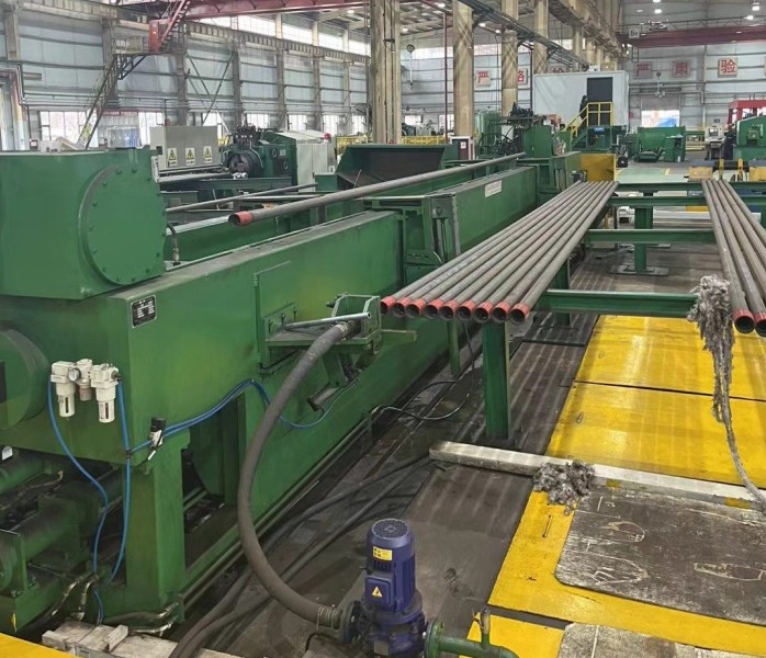
1. Pipe Specifications Determine the Machine Configuration
API 5CT covers technical delivery requirements for casing, tubing, pup joints and related materials. Its requirements address product dimensions, masses, wall thicknesses, grades and end finishes. These characteristics also form the starting point for hydrostatic testing equipment design.
The equipment supplier should review the complete product range before determining the machine layout.
| OCTG requirement | Influence on equipment design |
|---|---|
| Outside diameter | Determines test-head dimensions, sealing geometry and pipe support arrangement |
| Wall thickness | Affects pipe behavior under pressure and the specified test conditions |
| Pipe length and weight | Determines support spacing, transfer mechanism and machine-bed arrangement |
| Material grade | Must be matched to the applicable product specification and test procedure |
| End configuration | Determines sealing location and test-head design |
| Production output | Influences station arrangement, automation and cycle coordination |
A machine intended for a limited diameter range may use dedicated test heads, while a production line handling several sizes may require adjustable or interchangeable sealing assemblies.
The important point is to establish the actual minimum and maximum product dimensions, including the frequency of size changes. Designing only for the largest pipe can result in unnecessary costs or inefficient handling when smaller products make up most of the production volume.
2. Casing and Tubing End Conditions Affect Sealing Design
End sealing is one of the most important design considerations in an OCTG hydrostatic testing machine.
Casing and tubing may have different end preparations and connection types. These can include plain-end arrangements, non-upset tubing, external-upset tubing, integral-joint tubing and threaded casing connections.
The appropriate test-head arrangement depends on where a reliable sealing interface can be established without damaging the pipe end or interfering with its connection geometry.
Possible sealing arrangements include:
-
End-face sealing: Seals against a suitable pipe-end surface.
-
External radial sealing: Seals against the outside diameter.
-
Internal sealing: Uses an internal sealing element where the pipe geometry and test arrangement permit it.
Not every sealing method is suitable for every OCTG product. Threaded ends, upset sections and coupling configurations must be reviewed before selecting the sealing assembly.
The pressure load on the test head must also be considered. The basic relationship is:
[
F=Ptimes A
]
Where (F) is the axial force, (P) is internal test pressure and (A) is the effective pressurized area.
As pressure or effective diameter increases, the force acting on the test-head assembly increases. The locking mechanism, frame and supporting structure must therefore be designed for the actual operating conditions.
3. Hydraulic System and Testing Sequence
A typical Oil Pipe Hydrostatic Testing Machine performs the following operations:
Pipe loading and positioning → End sealing → Water filling and air removal → Pressure build-up → Pressure holding → Pressure release → Unloading
Each stage has a specific equipment function:
Water filling: A filling circuit introduces water into the pipe. Designated vent points allow displaced air to escape before high-pressure testing.
Pressure build-up: A high-pressure pump raises the internal pressure to the required test level. Pump capacity, valve response and hydraulic circuit design influence the pressure-rise time.
Pressure holding: Pressure instruments and PLC controls monitor the test condition during the specified holding period. The acceptance criteria must follow the applicable product specification and inspection procedure.
Pressure release: The system reduces pressure through its designed release circuit before the test heads retract.
For equipment handling different OCTG sizes and pressure requirements, the hydraulic arrangement should be evaluated across the complete operating range rather than selected from the maximum pressure rating alone.
4. Automation and Production-Line Integration
The required automation level depends on production volume, product variation and factory layout.
| Configuration | Typical application | Main consideration |
|---|---|---|
| Manual or semi-automatic handling | Lower output or frequent product changes | Operator access and changeover efficiency |
| Automatic loading and unloading | More consistent production flow | Transfer coordination and positioning accuracy |
| Multi-station arrangement | Production lines requiring overlapping operations | Balancing loading, testing and unloading cycles |
| Data-recording configuration | Manufacturers requiring digital inspection records | Pipe identification, pressure curves and result storage |
Automation should solve a defined production problem. For example, automatic positioning may reduce handling time, while multi-station operation may allow one pipe to be loaded as another completes its testing cycle.
Optional functions such as barcode identification, pressure-curve recording, automatic reporting and MES communication can be specified according to the manufacturer's quality-management system.
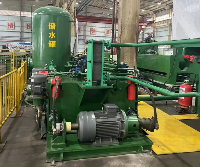
5. What Should Buyers Confirm Before Ordering?
An Oil Pipe Hydrostatic Testing Machine should be designed from a documented requirement sheet. The following information helps prevent an unsuitable configuration:
-
Minimum and maximum outside diameter, wall thickness and pipe length.
-
Pipe weight and material grades.
-
Plain-end, upset, threaded or coupled end conditions.
-
Required test pressures and holding periods.
-
Applicable product specifications and inspection procedures.
-
Target production output and expected size-change frequency.
-
Factory layout and transfer direction.
-
Required pressure monitoring, data storage and traceability functions.
One common purchasing mistake is specifying only the maximum diameter and pressure. This does not define the sealing interface, handling requirements, product mix or expected cycle time.
Another is assuming that one sealing arrangement will accommodate every casing and tubing connection. These details should be settled during engineering review, before machine manufacture.
6. Applicable Standards for OCTG Testing
API Specification 5CT is the primary product specification for casing and tubing. The 11th edition was published in December 2023, followed by Addendum 1 in May 2025 and Errata 3 in June 2026. Manufacturers should use the applicable controlled edition, including relevant updates, when establishing product and inspection requirements.
ISO 11960:2020 specifies technical delivery conditions for casing, tubing, pup joints, coupling stock and related materials. It covers connection types including SC, LC, BC, NU, EU and IJ. Its scope does not cover threading requirements.
API Specification 5B addresses threading, gauging and inspection of casing, tubing and line-pipe threads. It is relevant when evaluating threaded end geometry and thread inspection requirements, but it should not be confused with the hydrostatic test procedure itself.
The applicable product specification, purchase order and approved inspection procedure determine the actual test requirements. A machine's maximum pressure rating alone does not establish compliance.
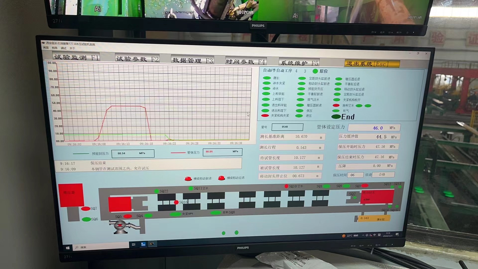
A suitable OCTG pipe testing machine must match the manufacturer's complete product range, not just one nominal casing or tubing size. Diameter, wall thickness, length, end configuration, test pressure and production output all influence the hydraulic, mechanical and automation design.
For oilfield pipe production, the most effective equipment configuration is one that provides reliable sealing, controlled hydrostatic testing and practical integration with the production line. These requirements should be reviewed together before the machine is manufactured.