








If an ultrasonic pipe inspection system starts producing false rejects or missing real defects, replacing probes is rarely the right first step. In most steel pipe mills, inspection errors originate from unstable calibration, probe misalignment, poor water coupling, encoder timing errors, or pipe geometry changes—not from the ultrasonic pipe testing machine itself. Identifying which part of the inspection process has become unstable is the fastest way to restore reliable detection and reduce unnecessary production losses.
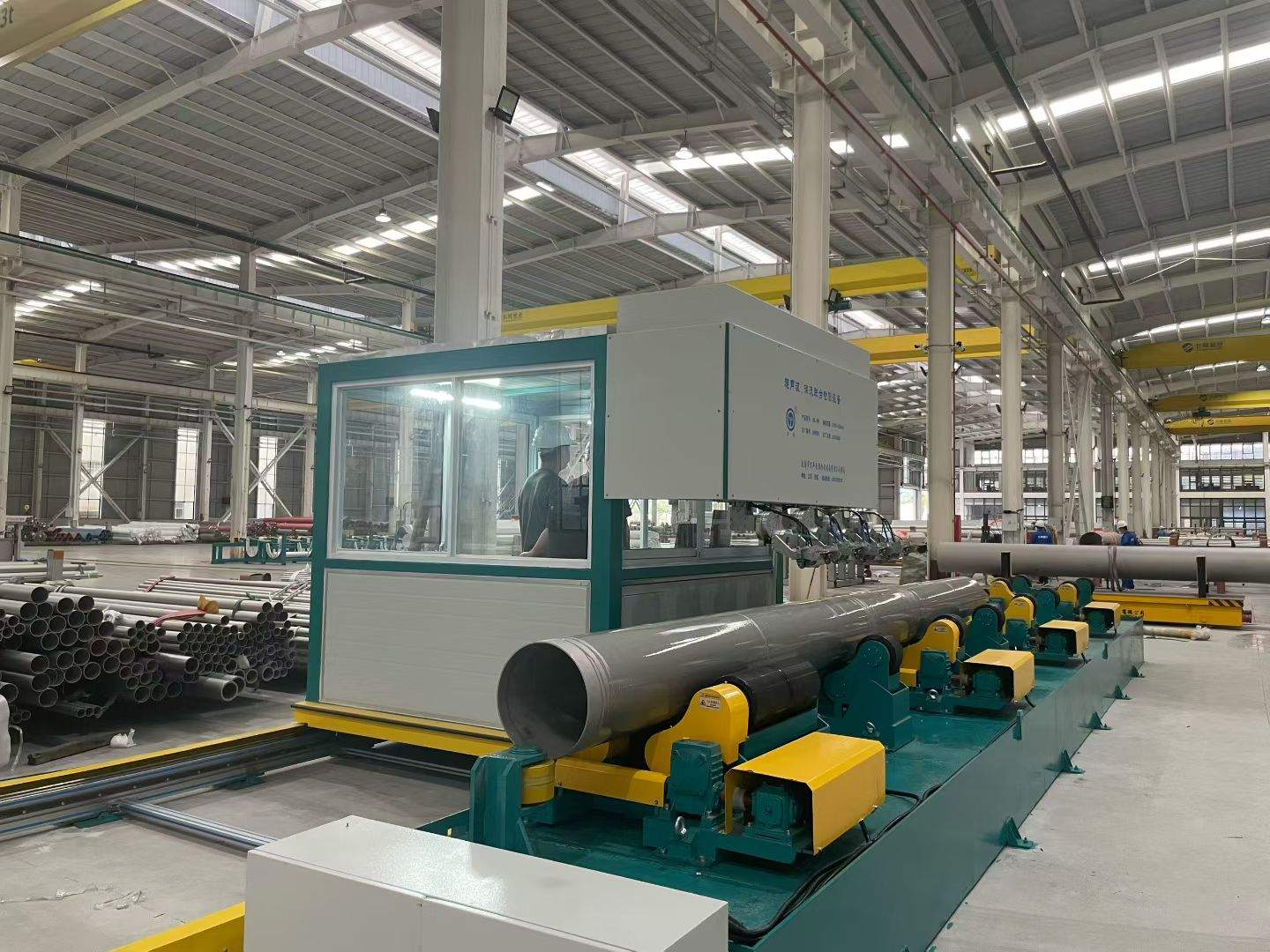
The Biggest Mistake: Treating Every False Indication as a Probe Problem
When false indications appear repeatedly, many maintenance teams immediately replace probes or recalibrate electronics. In reality, probe failure accounts for only a small percentage of recurring inspection issues.
Experienced mills usually investigate the inspection system in the following order:
| Inspection Area | Typical Root Cause | Production Impact |
|---|---|---|
| Calibration | Reference notch inconsistency | Entire production batch shifted |
| Mechanics | Pipe vibration or eccentric rotation | Random false echoes |
| Water coupling | Air entrainment or unstable water film | Signal dropouts |
| Pipe geometry | Ovality, weld reinforcement, end deformation | Geometric reflections |
| Synchronization | Encoder slip or scan timing drift | Defect location errors |
| Signal processing | Incorrect gate or filtering parameters | False reject / missed defect |
Notice that only one of these categories directly involves the ultrasonic probe itself.
Error 1 — Calibration Drift Caused by Poor Reference Standards
The most expensive inspection errors often begin long before the first production pipe enters the inspection line.
Many mills verify instrument response every shift but overlook whether the reference pipe remains dimensionally stable.
Typical problems include:
- Reference notch wear after repeated scanning
- Poorly machined EDM notches
- Surface corrosion on calibration standards
- Temperature differences between calibration pipe and production pipe
- Using one calibration pipe across multiple wall thicknesses
A calibration offset of only a few decibels may appear insignificant, yet over thousands of pipes it can substantially increase either false rejection or missed discontinuities. Studies in steel pipe inspection have shown that inconsistent calibration standards can produce large inspection variability across operators and production lines.
Engineering Best Practice
Instead of scheduling calibration solely by elapsed time, define recalibration limits based on:
- Number of inspected pipes
- Water temperature variation
- Probe replacement
- Mechanical adjustments
- Shift change after maintenance
Error 2 — Mechanical Positioning Errors Hidden as Ultrasonic Problems
Many inspection engineers spend hours adjusting gain when the real problem lies in mechanics.
Common examples include:
- Roller runout
- Pipe bouncing
- Scanner vibration
- Uneven rotation speed
- Encoder backlash
- Axial wandering
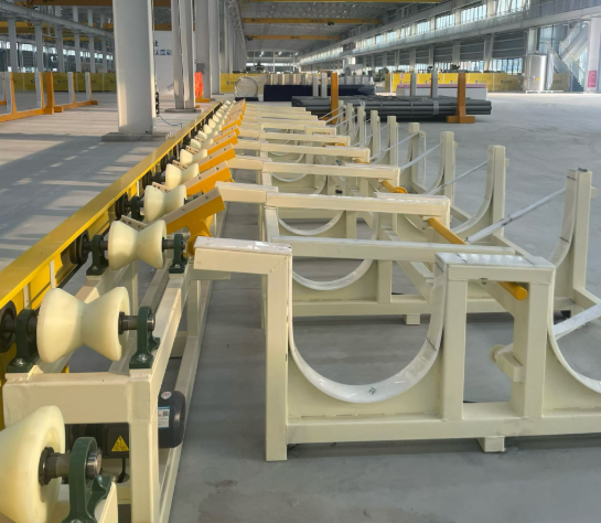
Even high-end ultrasonic pipe inspection equipment cannot compensate for unstable probe-to-surface distance.
Small lift-off variations alter beam incidence angles, changing reflected energy before software even begins signal analysis.
Error 3 — Water Coupling Instability
Water coupling problems rarely produce complete signal loss.
Instead, they create intermittent amplitude fluctuations that are much more difficult to diagnose.
Typical causes include:
- Air bubbles entering spray manifolds
- Contaminated filtration systems
- Uneven nozzle distribution
- Excessive water turbulence
- Incorrect nozzle angle
- Pump pressure fluctuation
Operators sometimes increase gain to compensate.
Unfortunately, increasing gain raises background noise together with useful echoes, reducing signal-to-noise ratio instead of improving inspection reliability.
Error 4 — Ignoring Pipe Geometry Effects
Steel pipes are rarely geometrically perfect.
Inspection algorithms usually assume:
- Constant wall thickness
- Stable curvature
- Uniform outside diameter
- Constant weld profile
Production reality is different.
Minor variations in:
- Ovality
- End expansion
- Weld reinforcement
- Seam offset
- Wall eccentricity
can all generate geometric reflections that resemble defect signals. Distinguishing geometry echoes from genuine discontinuities remains one of the most challenging aspects of ultrasonic interpretation.
Error 5 — Synchronization Errors Between Motion and Data Acquisition
Modern ultrasonic testing machinery for pipes depends on precise synchronization between:
Pipe Movement
│
Encoder Position
│
Trigger Timing
│
A-Scan Collection
│
Defect Mapping
If encoder pulses drift because of wheel slip or mechanical backlash:
- defect position shifts
- C-scan images distort
- multiple channels become misaligned
- automatic defect tracking becomes unreliable
Interestingly, ultrasonic signals themselves may remain perfectly clean.
Only the positional information becomes incorrect.
Error 6 — Excessive Digital Filtering
Modern inspection software offers powerful filtering tools.
These improve display quality but can unintentionally remove useful information.
Common mistakes include:
- aggressive smoothing
- excessive averaging
- narrow band-pass filtering
- overuse of automatic suppression
The result is cleaner displays but poorer defect characterization.
Experienced Level III engineers usually prefer moderate filtering combined with higher-quality raw signals instead of relying on software to "clean" noisy data.
Engineering Trade-Off: Sensitivity vs Production Stability
One misconception is that maximum sensitivity always delivers the highest inspection quality.
In production environments, this is rarely true.
| Strategy | Advantage | Drawback |
| Maximum sensitivity | Detects very small reflectors | High false reject rate |
| Moderate sensitivity with stable mechanics | Consistent production | Better repeatability |
| Heavy digital filtering | Cleaner displays | Potential loss of weak indications |
| Higher scanning speed | Increased throughput | Reduced sampling density |
| Lower scanning speed | Better signal quality | Reduced productivity |
High-performing mills optimize the entire inspection system rather than maximizing a single parameter.
A Useful Diagnostic Sequence Before Blaming the Equipment
When recurring inspection errors appear, experienced maintenance teams typically investigate in this order:
- Verify calibration standard integrity.
- Check encoder accuracy and synchronization.
- Inspect probe alignment and stand-off distance.
- Confirm water flow stability and coupling quality.
- Measure pipe rotation stability.
- Review scan parameter changes.
- Compare defect patterns across channels.
- Replace probes only after eliminating system-level causes.
This sequence minimizes unnecessary downtime while addressing the most common root causes first.
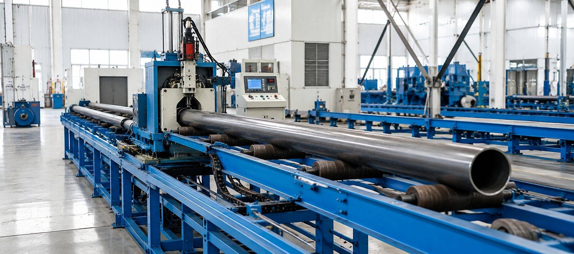
The majority of inspection errors in ultrasonic pipe testing equipment originate from interactions between calibration, mechanics, coupling, geometry, and data processing—not from a defective ultrasonic instrument. Mills that consistently achieve low false rejection rates treat ultrasonic inspection as an integrated electromechanical system rather than a standalone NDT process. The strongest performance comes from stable calibration standards, repeatable mechanical positioning, disciplined synchronization, and conservative signal processing, allowing genuine defects to remain distinguishable from normal production variability.