








Optimizing Ultrasonic pipe inspection equipment through probe configuration is primarily a matter of matching the acoustic beam to the pipe geometry, defect orientation, material condition, and production speed—not simply increasing probe frequency or adding more probes. The most effective configuration controls five variables: probe type, beam angle, frequency and aperture, circumferential arrangement, and probe-to-pipe coupling. For automated steel pipe inspection, the probe layout should provide sufficient overlap and stable sensitivity across the full inspection zone while minimizing dead zones and excessive noise. Standards such as ASTM E213 and ISO 10893-10 recognize different ultrasonic techniques, including conventional and phased-array approaches, depending on the inspection objective.
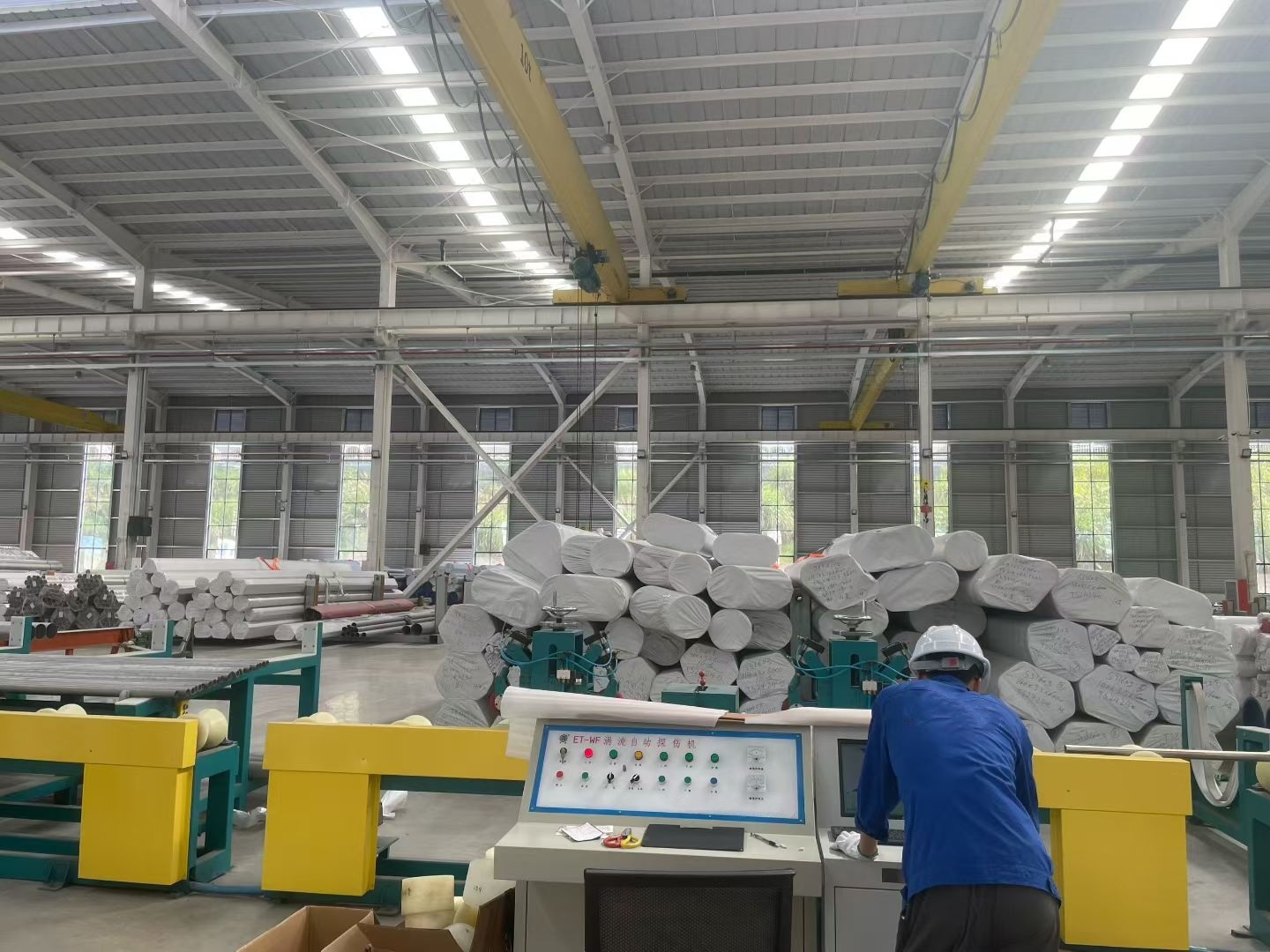
1. Start With Defect Orientation, Not Probe Selection
The first engineering decision is what defect orientation the system must reliably detect.
A longitudinal defect and a transverse defect do not present the same reflector geometry to an ultrasonic beam. A probe configuration that performs well for one orientation can produce weak or inconsistent responses for another.
For automated full-peripheral steel tube inspection, ISO 10893-10 specifically addresses detection of longitudinal and/or transverse imperfections using ultrasonic shear-wave techniques generated by conventional or phased-array technology.
A practical configuration sequence is:
Required defect orientation → pipe geometry → beam direction → probe angle → frequency/aperture → circumferential coverage → calibration
This order matters. Choosing a probe first and trying to adapt the inspection strategy afterward often creates unnecessary gain, poor coverage, or unstable indications.
Probe configuration should therefore be defined by:
| Engineering factor | Configuration decision | Main effect |
|---|---|---|
| Defect orientation | Longitudinal / transverse / other | Beam direction |
| Pipe OD and wall thickness | Probe size and focal geometry | Coverage and penetration |
| Material and grain structure | Frequency selection | Attenuation and SNR |
| Surface condition | Contact shoe / immersion / water column | Coupling stability |
| Production speed | Number and spacing of probes | Scan coverage |
| Required sensitivity | Aperture, frequency, gain | Detectability |
| Inspection standard | Reference reflectors and procedure | Acceptance reliability |
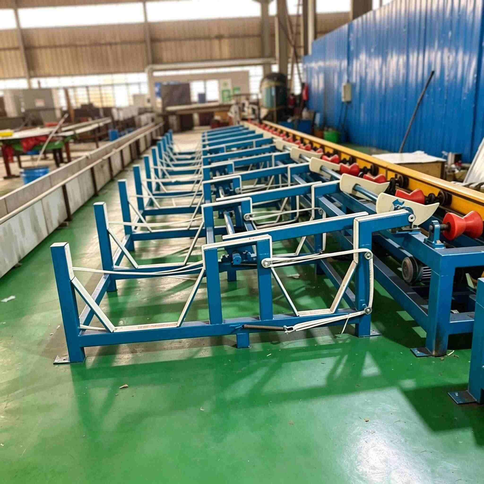
2. Optimize Beam Orientation Around the Pipe
For steel pipe inspection, probe orientation is usually more important than simply increasing ultrasonic energy.
A beam should intersect the expected defect at an angle that produces a strong, repeatable reflection. For this reason, automated ultrasonic pipe testing equipment commonly uses multiple probes or probe assemblies arranged around the pipe circumference.
For example, when longitudinal imperfections are the primary target, the ultrasonic beam must be oriented so that the reflector presents a favorable acoustic interface. For transverse imperfections, the probe arrangement must be changed accordingly.
This is also why a four-probe system is not automatically better than a two-probe system. The relevant question is whether the arrangement provides adequate circumferential coverage, overlap, and defect sensitivity at the required line speed.
3. Select Frequency From the Material and Wall Thickness
Higher frequency does not automatically mean better inspection.
Increasing frequency can improve sensitivity to small reflectors, but it also increases attenuation and scattering, particularly in coarse-grained, alloyed, or otherwise acoustically difficult materials. A frequency that performs well on a fine-grained carbon-steel tube may become counterproductive on a material with substantially higher attenuation.
The engineering objective is therefore to maximize:
Signal-to-noise ratio + penetration + resolution
rather than frequency alone.
Probe aperture also matters. A larger active aperture can improve beam characteristics and energy transfer, but physical access, pipe curvature, and probe footprint impose practical limits. On small-diameter pipes, an oversized probe can produce poor conformity and unstable coupling.
4. Match Probe Geometry to Pipe Curvature
A flat probe on a curved pipe surface does not behave like the same probe on a flat calibration block.
As pipe diameter decreases, surface curvature becomes increasingly important. The probe shoe, delay line, or coupling arrangement should therefore be designed around the actual pipe OD range rather than treated as a universal component.
For production equipment covering a wide diameter range, engineers should evaluate:
- Probe shoe curvature
- Contact area
- Water path or standoff
- Beam entry point
- Coupling stability
- Probe wear
- Adjustment repeatability
A mechanically simple probe holder that maintains constant geometry during production is often more valuable than a theoretically superior probe that requires frequent manual adjustment.
5. Use Probe Overlap to Protect Against Coverage Gaps
Probe quantity should be calculated from the required inspection coverage—not selected simply because a certain number of probes is conventional.
For circumferential inspection, the arrangement should account for the effective beam width, pipe diameter, probe position, and required overlap.
A simplified engineering concept is:
Probe spacing < effective inspection width
with sufficient overlap to compensate for variations in pipe position and beam response.
The critical point is that geometric coverage and effective acoustic coverage are not identical. Two adjacent probes may appear to cover the circumference geometrically while leaving a sensitivity gap between their actual acoustic fields.
This should be verified using the reference standard rather than inferred from mechanical drawings.
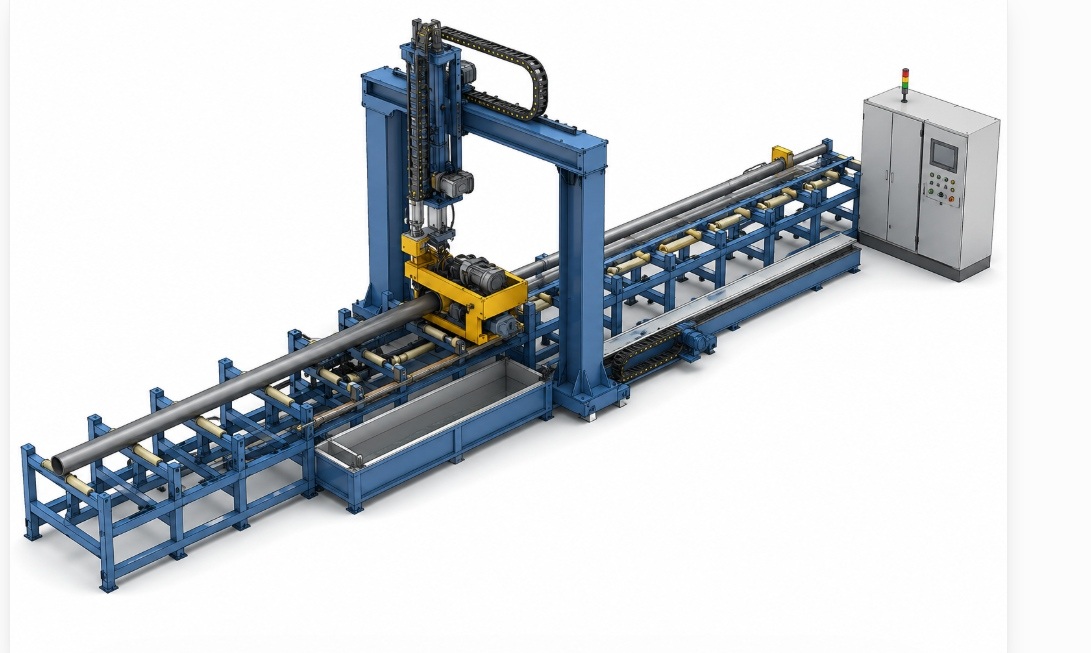
6. Control Probe-to-Pipe Coupling
In high-speed ultrasonic testing machinery for pipes, coupling instability is one of the most common reasons a theoretically good probe configuration performs poorly in production.
Water coupling systems should maintain a stable acoustic path despite:
- Pipe diameter variation
- Ovality
- Surface roughness
- Pipe vibration
- Production speed changes
- Probe wear
- Water contamination
If coupling varies, increasing gain is usually the wrong solution. It can raise background noise and false indications without restoring the lost inspection reliability.
A better approach is to stabilize the mechanical and hydraulic conditions first, then recalibrate sensitivity.
7. Validate the Configuration With the Reference Standard
Probe configuration should be treated as part of the inspection procedure, not merely as machine hardware.
ASTM E213 describes ultrasonic examination of metal pipe and tubing using pulse-reflection methods and includes conventional and phased-array techniques. It also identifies artificial reflectors on reference standards as a primary means of standardizing the ultrasonic system.
A robust commissioning sequence is:
Install probe array → establish coupling → set beam geometry → calibrate on reference pipe → verify each probe independently → verify overlap → run at production speed → confirm signal stability → lock mechanical settings
The final verification should be performed under conditions representative of actual production. A probe configuration that passes calibration at low speed but loses sensitivity during continuous high-speed scanning is not an optimized configuration.
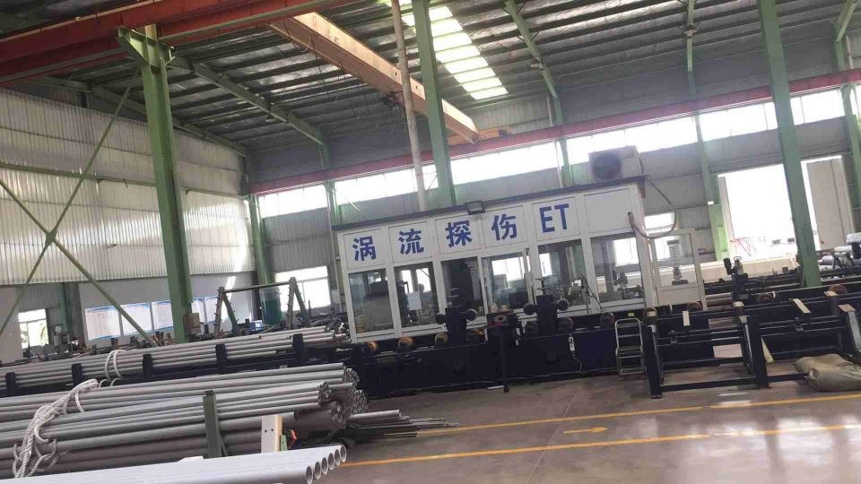
8. Conventional Probes vs. Phased Array
Phased-array technology can provide greater flexibility in beam steering, focusing, and inspection coverage. ISO 10893-10 explicitly permits both conventional and phased-array ultrasonic generation for automated full-peripheral testing.
However, phased array should not be adopted simply because it is more advanced.
For a stable production line with a well-defined pipe range and defect orientation, a conventional multi-probe arrangement may offer lower complexity, easier maintenance, and predictable calibration.
Phased array becomes more attractive when the inspection window is broad, pipe specifications vary significantly, or multiple beam angles and inspection conditions must be controlled electronically.
The correct question is therefore not “Which technology is newer?” but “Which probe architecture provides the required detection capability with the lowest operational complexity?”
Engineering Takeaway
The best probe configuration for Ultrasonic pipe inspection equipment is the one that produces stable, repeatable defect responses across the entire inspection zone at actual production speed.
In practice, optimization should follow this priority:
Defect orientation → beam geometry → pipe curvature → frequency/aperture → circumferential coverage → coupling → production-speed validation
Adding probes, increasing frequency, or increasing gain without addressing these relationships rarely produces a proportional improvement in inspection quality. For steel pipe manufacturers, a properly engineered probe array can improve detection reliability while simultaneously reducing false calls, calibration drift, and unnecessary system complexity.